Assembly
Once you received all parts, you can start assembling the block.
Important
The steps and component names are based on the
rev4.1board. If you have a different one, make sure to check the schematic.
PCB
Besides the components, you will also need a soldering iron, solder, and additional tools like tweezers.
Many of the components are surface mounted (SMD), feel free to use heat reflow or other methods, but I found that using a fine soldering iron tip works fine as well.
You can use the Schematic (PDF) as a reference for components.
Tip
You can follow the assembly order listed below, to validate the components as you go along
Main Controller
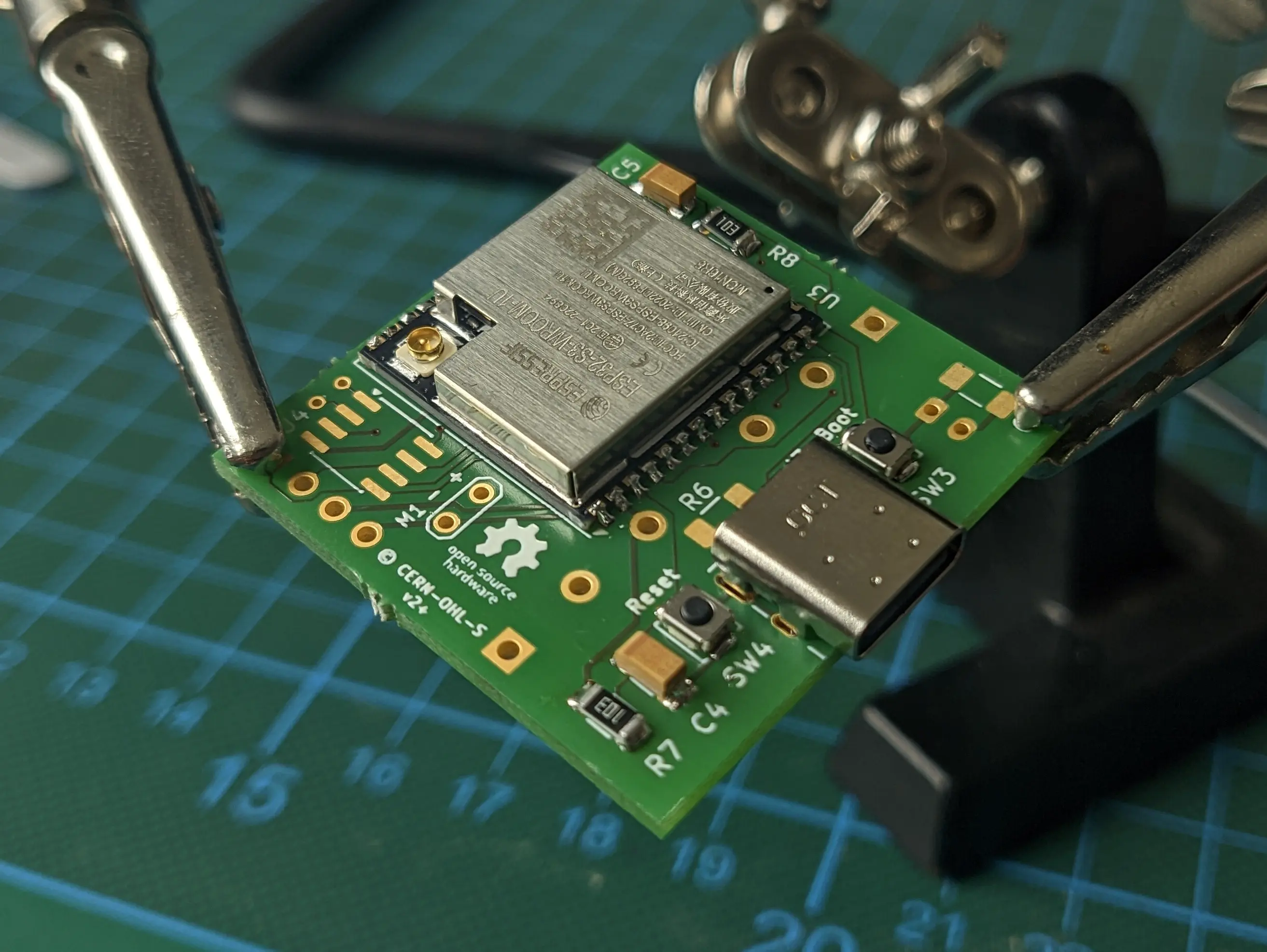
We’ll start by soldering on the ESP32S3 WROOM (U3).
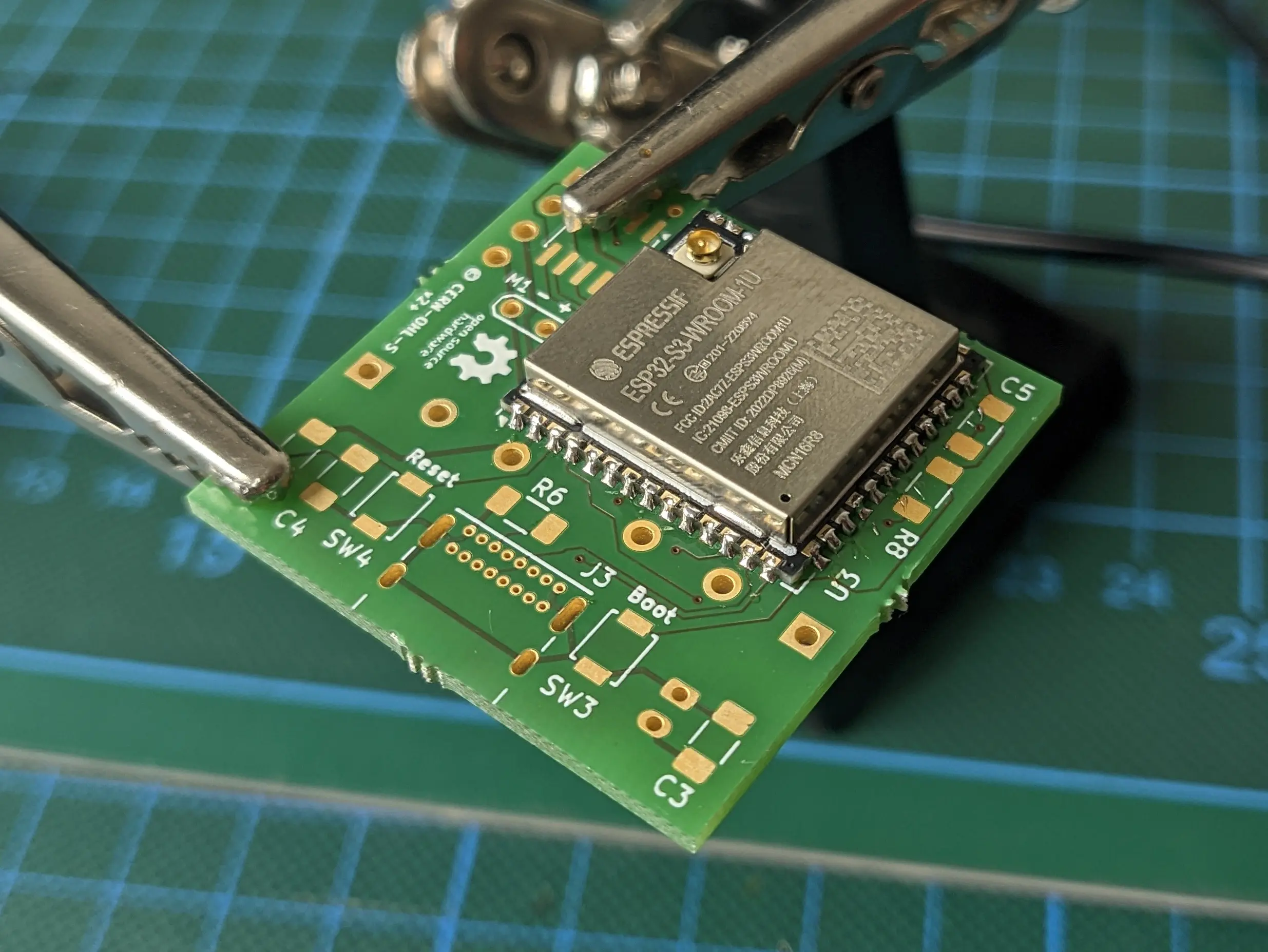
Afterwards, we’ll add the USB408 USB-C port (J3) and both the boot and reset button assembly (SW3, SW4, C4, C5, R7, R8).
Tip
If you want to ensure the ESP is functioning properly, you can hook up the 3V3 and GND lane, which is exposed through the display interface to an external powersupply and connect a USB cable between your computer and the device. You should see that the device is showing up in
lsusbas an Espressif device Which you can control using the Boot and Reset buttons.
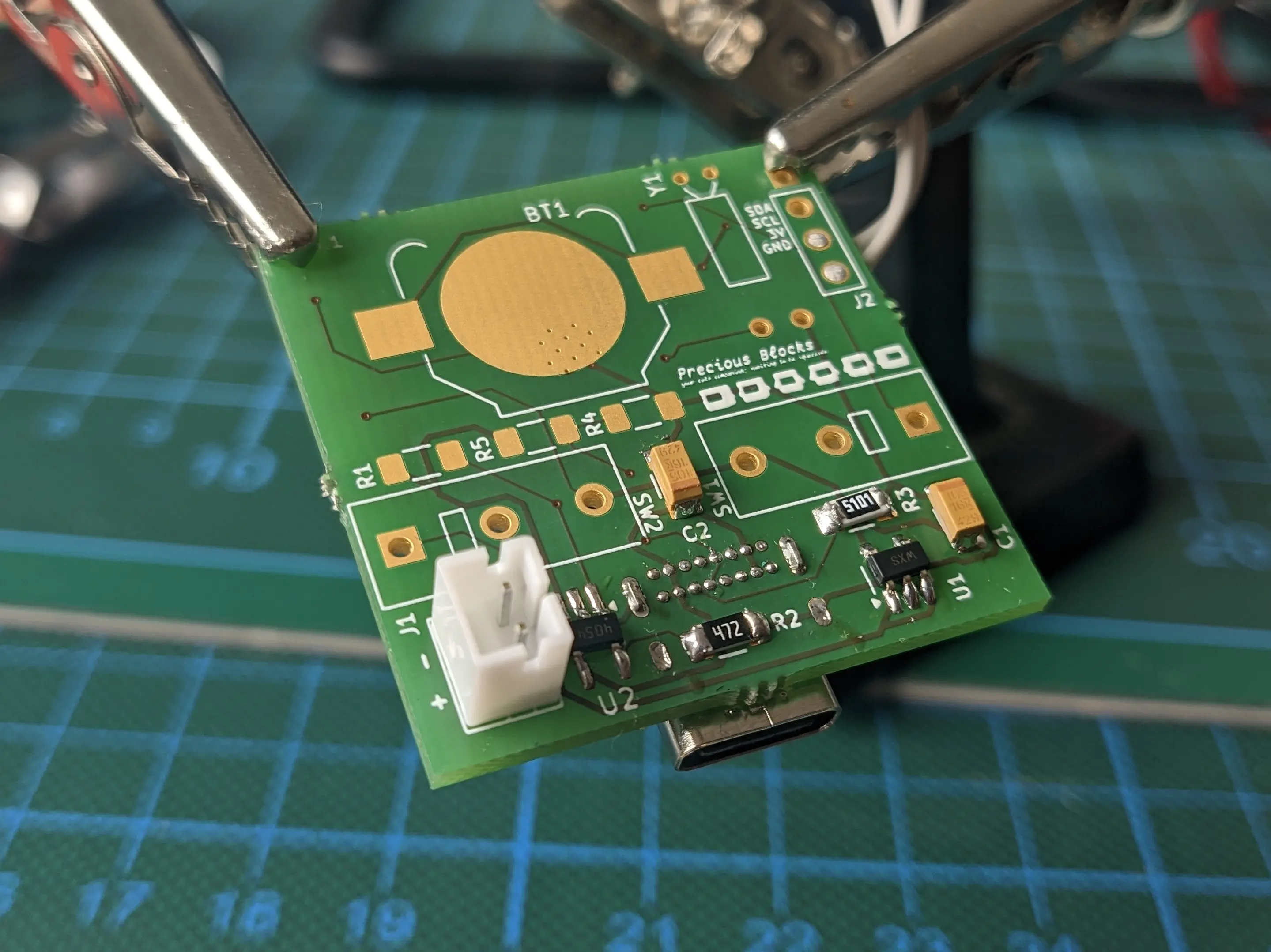
Power Management
With the ESP, being the most complicated part, out of the way, we can move on to the on-board power-management.
This includes the voltage converter MIC5504 (U1), battery charge controller STC4054GR (U2), battery controller port JST PH-K (J1) and R2, C2, R3, R6, C1, C2, C3,.
Tip
To confirm if everything is working as expected you can connect the battery to the battery connector and plug the device back into your computer. It should show up the same way it did before, but without requiring an external power source.
Required Peripherals
With the base system done, we can move on to the required peripherals.
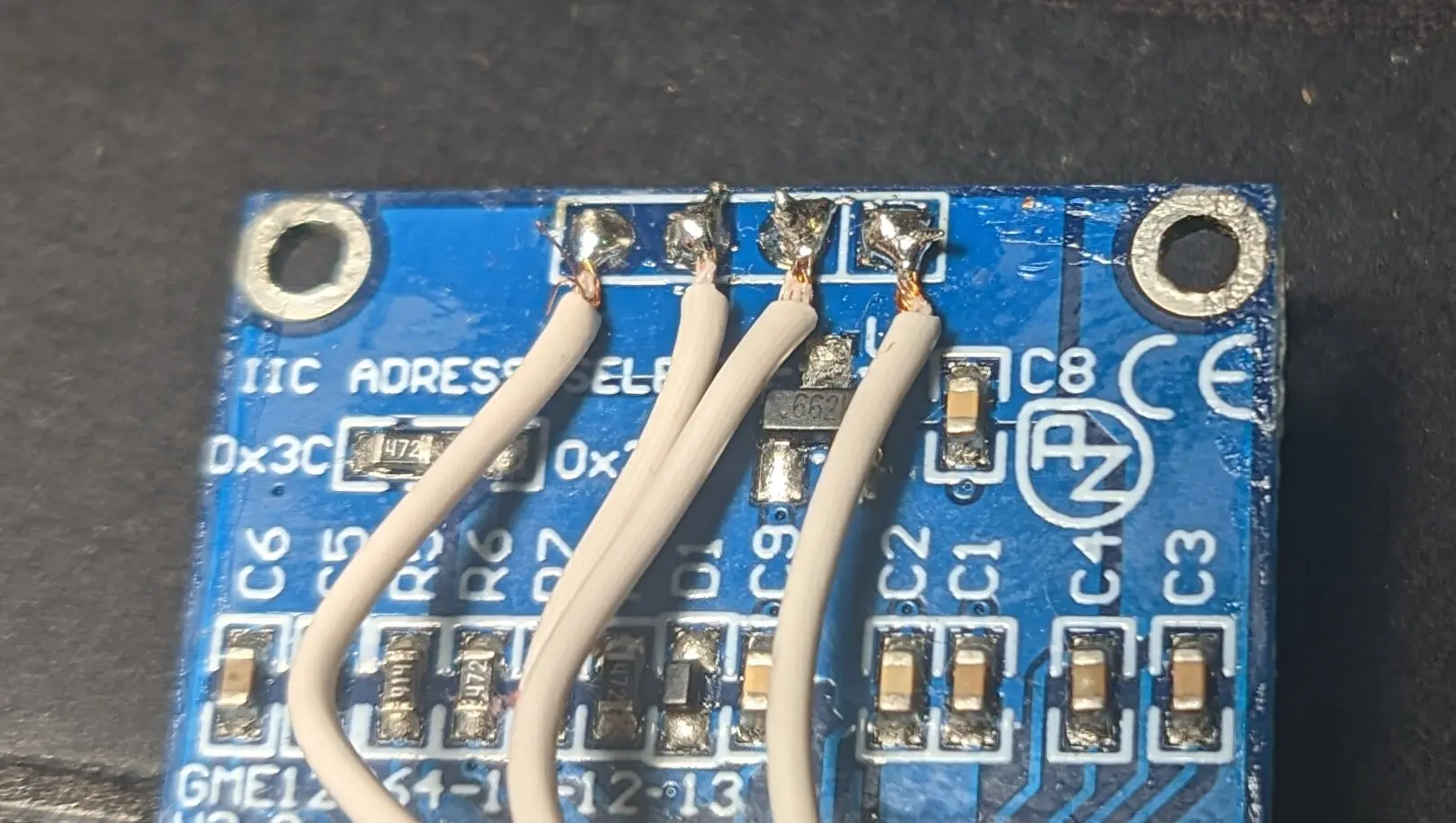
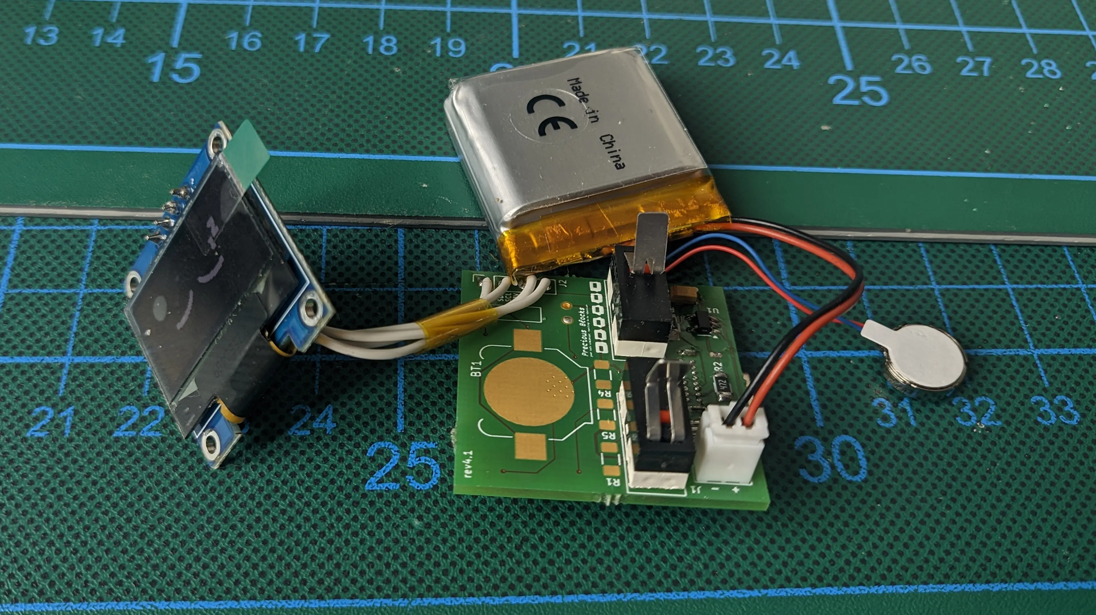
Before hooking up the display, I would recommend unsoldering the display pin header, to make more space in the upper part of the case, where the battery will be stored.
After unsoldering it, solder on four wires (roughly 4cm long) and hook them up to the top of the PCB (J2).
Tip
If you are impatient, you can already test the display by flashing the firmware onto the device and powering it up / resetting the device (See below)
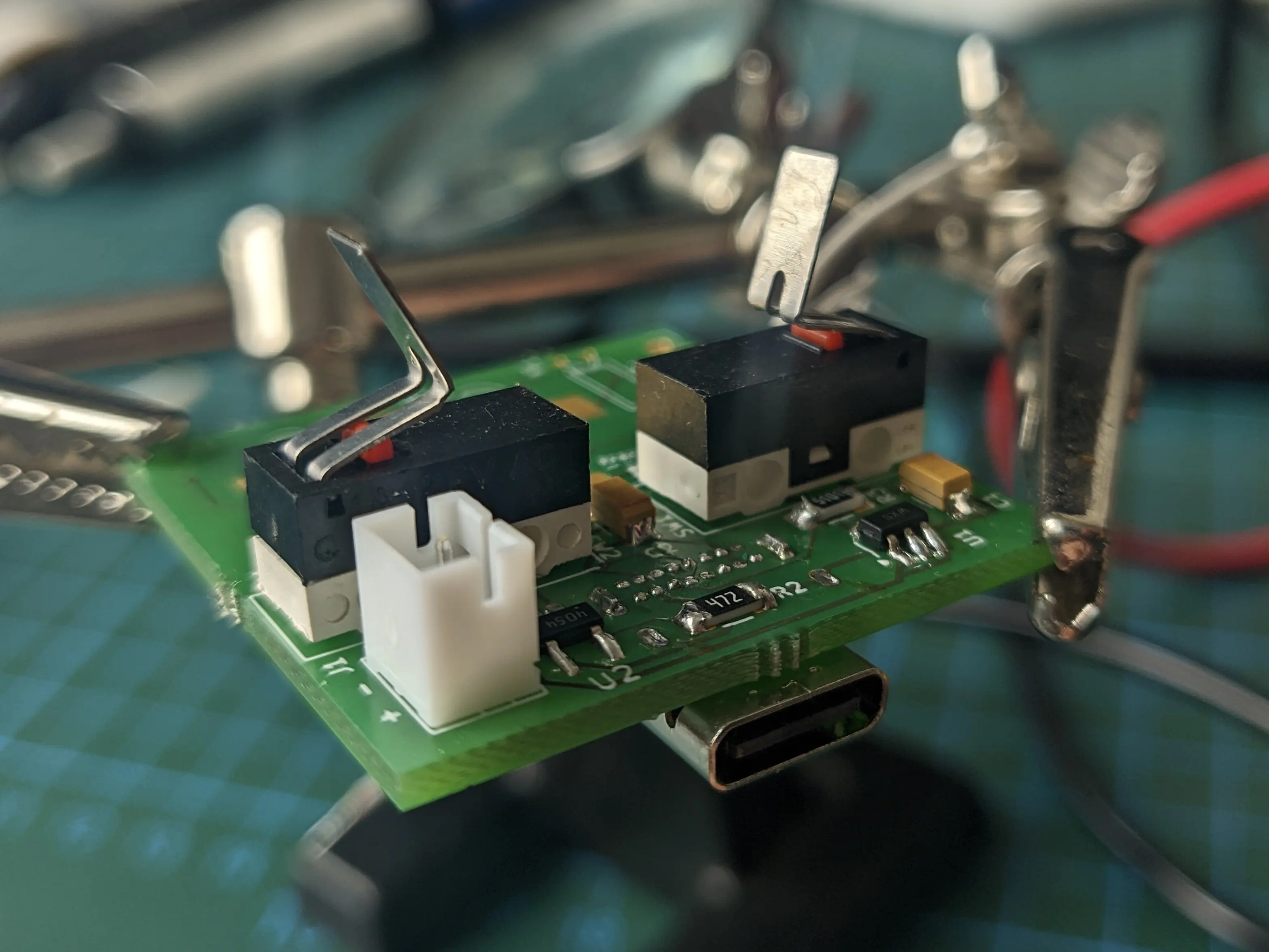
You will also want to solder on both limit switches (SW1, SW2), as they are required to turn on the block.
Make sure to bend the metal plate on the switches about 90 degree at the midpoint, to give the arms something to interface with.
Feel free to experiment with different angles for different button push-back force.
Tip
If you’ve already flashed the firmware, you should now be able to wake the block from sleep
Additionally, you should hook up the vibration motor to the pins on the bottom.
Tip
When you wake the block, by pressing both arms the motor should vibrate indicating that it is working properly
Flashing the firmware
You should now be able to flash the firmware onto the PCB in download mode.
Note that you have to hold the Boot button, while pressing the Reset button to enter the download mode, when a battery is connected.
If you flash the block for the first time, espflash might complain that the block is stuck in download mode and it is waiting for a response.
In this situation, check if the firmware flash process was successful,
and manually reset the block.
This should not be required from now on.
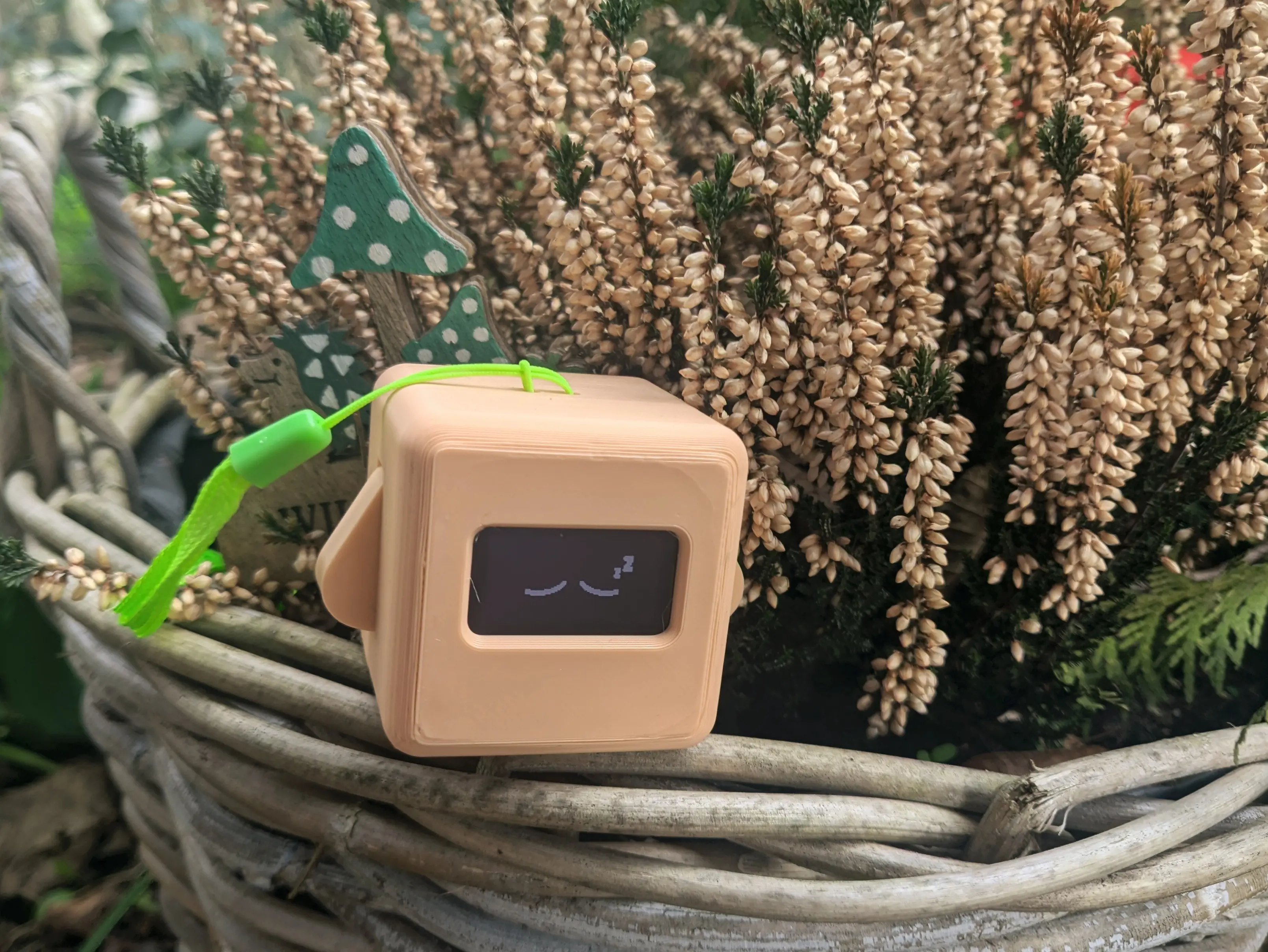
Once you restart the block, you should see the sleeping eyes shown on the display and be able to interact with it using the arms.
Additional Peripherals (recommended)
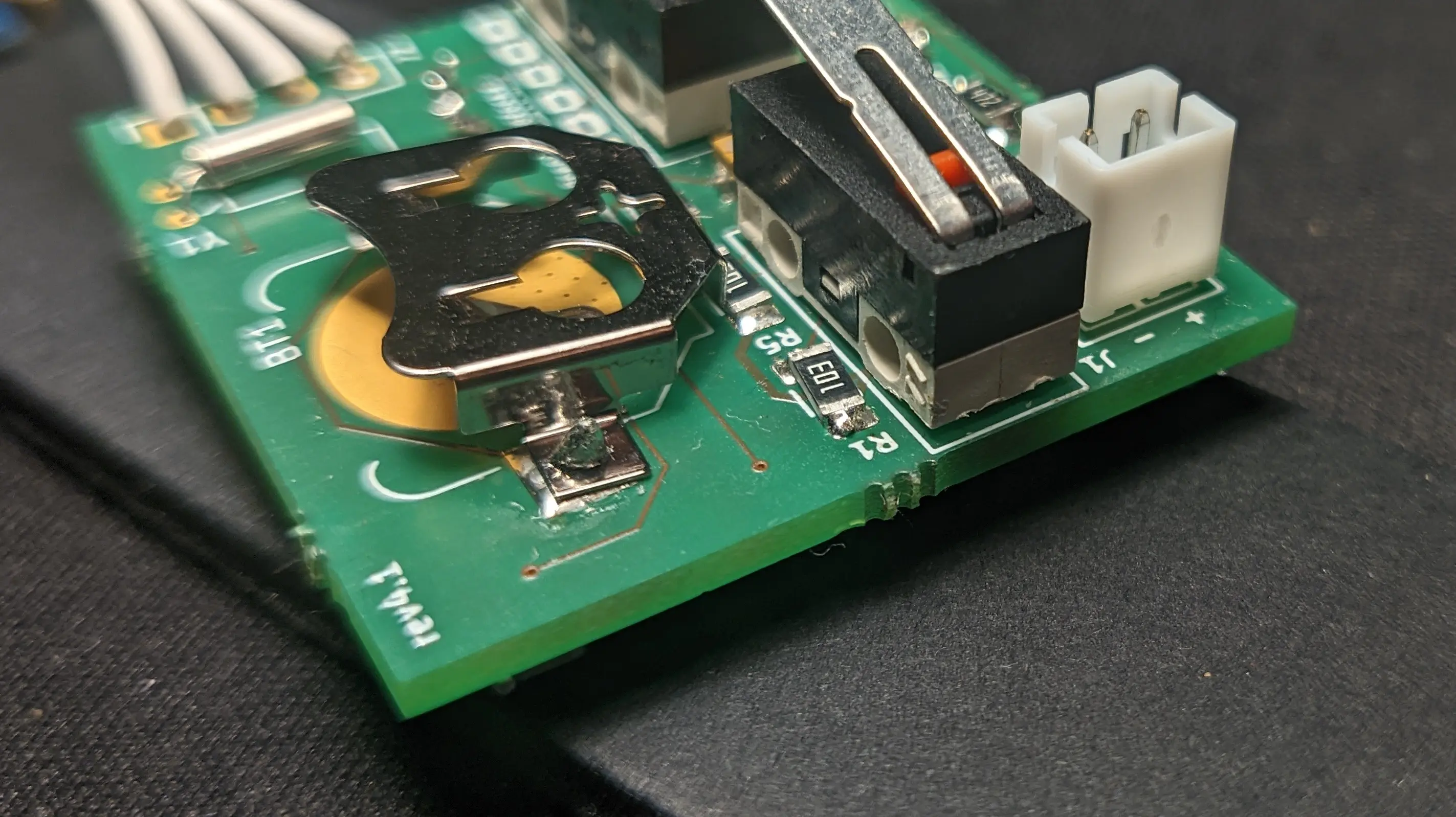
Finally, you can solder on the external clock module,
by soldering on the PCF8523T (U4), the oscillator (Y1), and the coin cell battery holder (BT1).
You also have to add a coin cell battery (CR1220) as the device won’t turn on otherwise.
You should also solder up the resistors required for battery charge monitoring (R1, R4, R5).
Important
Furthermore, you should hook up an external wifi antenna to the ESP antenna port if you want to use WiFi.
And make sure the Li-Ion battery is connected.This should leave you with a fully working PCB, ready to be mounted inside the case
Case
Both the front and back have recesses to fit four magnets.
The magnets are used to align the two shell pieces and ensure they stay together.
You can use instant glue to glue the cubes into the front of the case.
Afterwards match the magnet orientation for the back, so the front attracts the back.
And glue them in place by pushing them into the recess on the back using a wooden rod (or a different non-magnetic rod).
Tip
You should do a test fit after the glue dried to make sure you got the orientations correct (trust me).
If one of the magnets is wrong, use a pair of parallel pliers (or comparable) to remove it from the front part by wiggling it.
With the magnets in place, you can glue the vibration motor into the recess in the bottom of the back case.
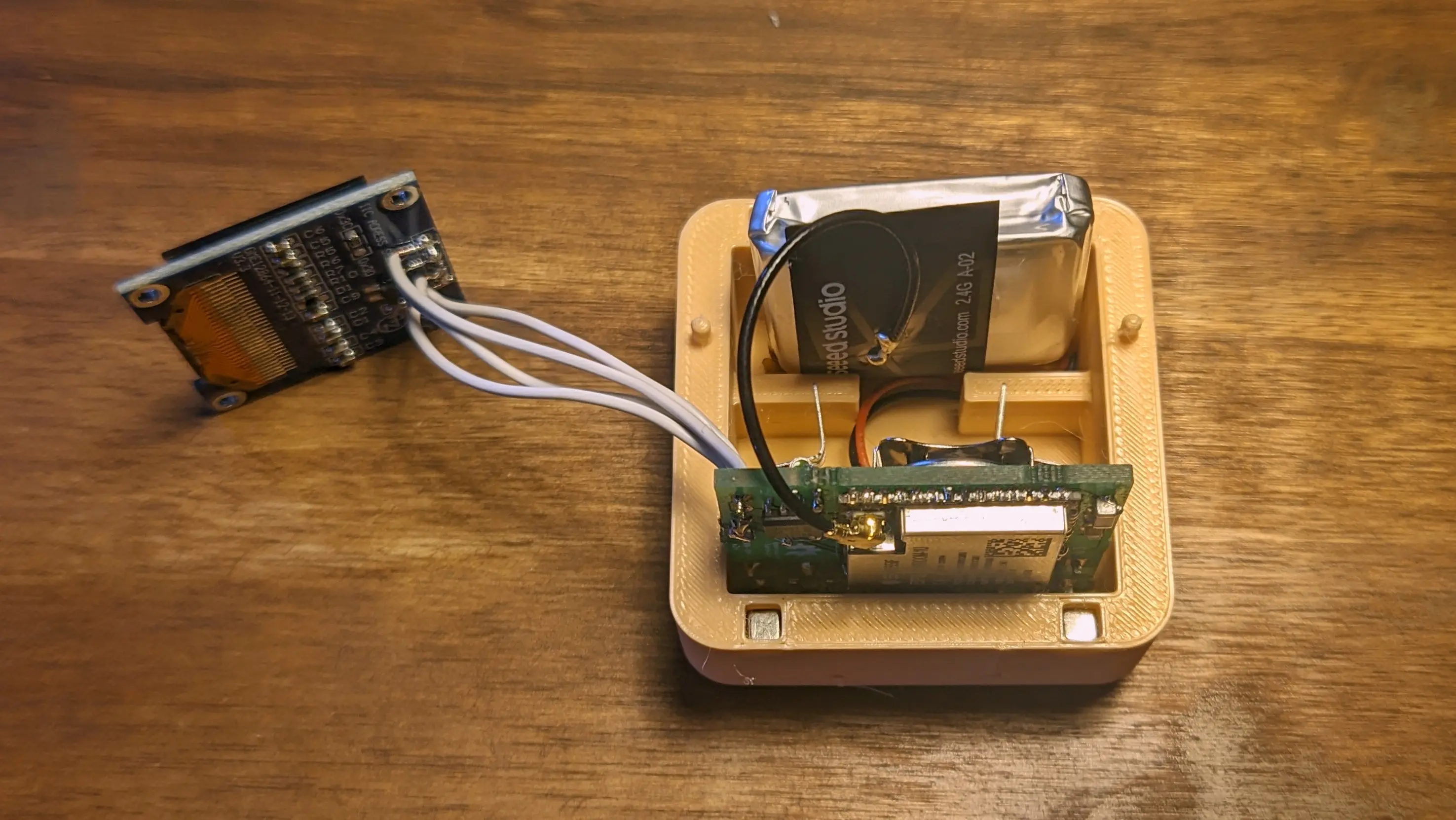
You can also reconnect the battery (if you removed it) and use some sticky-foam-tape to glue it into the box on the top.
Afterwards, slide in the pcb into the back of the case, making sure to align the USB port on the back.
Tip
You can stick the WiFi antenna to the LiPo using electrical tape, it should perfectly fit into the top, although you might have to bend the cable a little to allow the front to go on properly
To install the display, push one side into the recess and slowly press down on the opposite side to snap it in place.
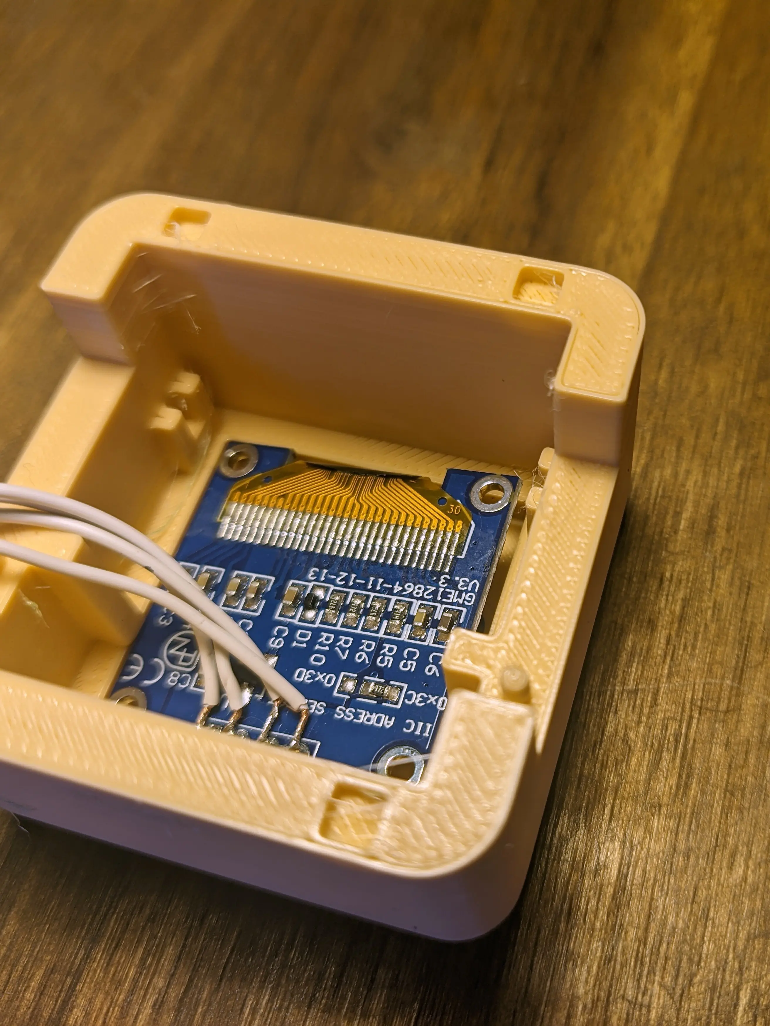
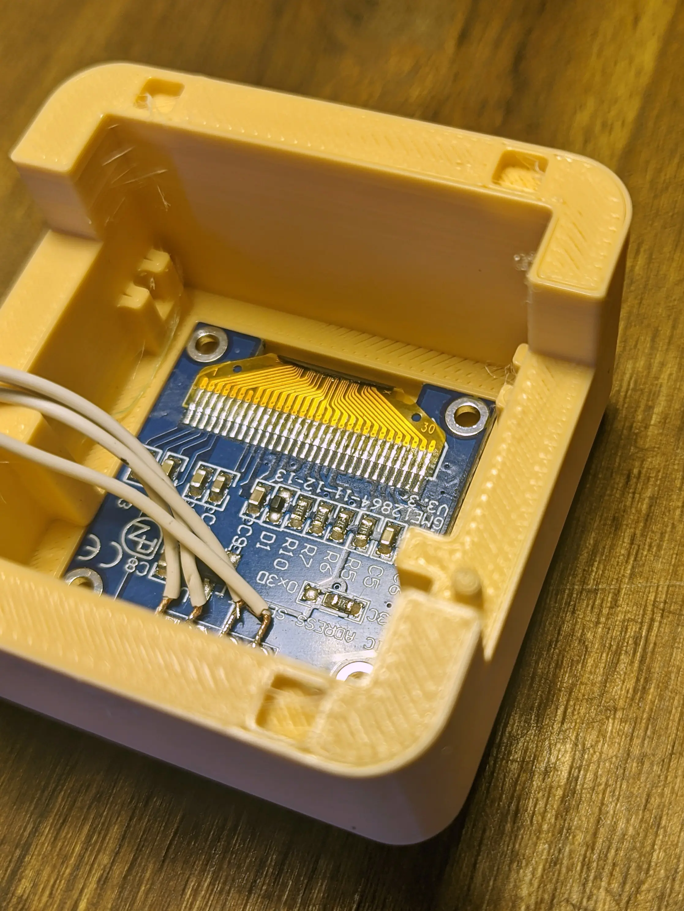
Tip
You can remove the display by applying even pressure (i.e. using your thumb) to it from the front of the case. Make sure not to overdo it though, as you might crack the fragile display components.
Before sliding on the front, push the arms onto the pins on the back,
making sure the arms interface with the limit switches on the PCB.
Now, push on the front case and make sure the PCB fits into the PCB mount in the front half.
Lastly, you can push the lanyard wire through the hole on the top and fix it in place by looping it through itself.
Note
That is it - you have fully assembled your own Precious Block
Enjoy 🌸